
Wiring Diagram Of Ignition Coil
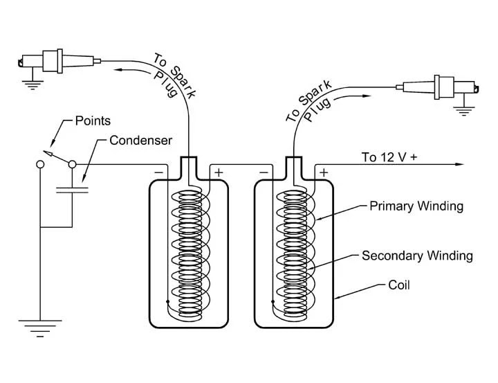
The ignition coil condenser wiring diagram is a visual representation of the electrical connections between the ignition coil and the condenser in a vehicle's ignition system. This diagram helps understand the proper wiring and connection of these components, which are crucial for the ignition system to function effectively. It provides a convenient reference for troubleshooting and diagnosing.
Weak Ignition Coil Causes Misfire
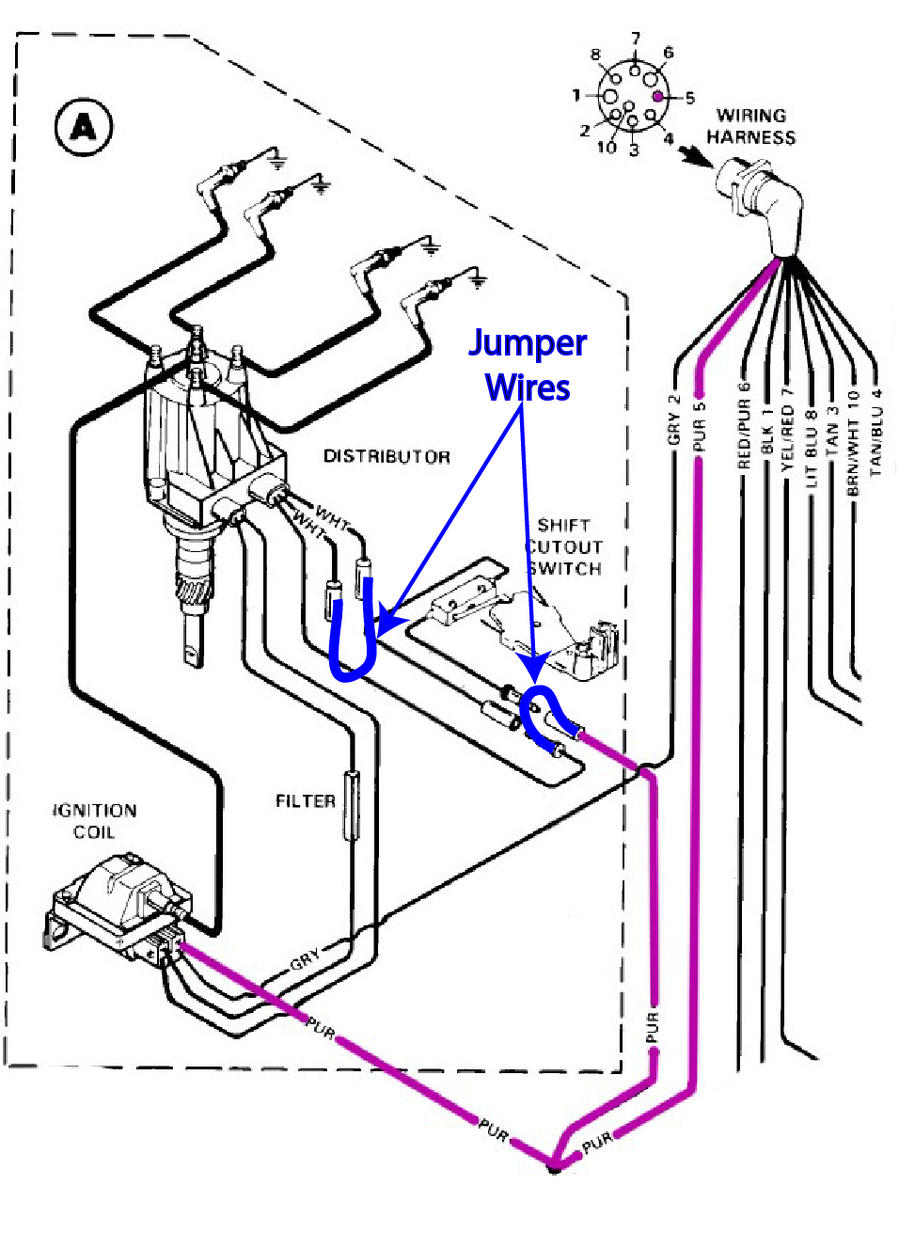
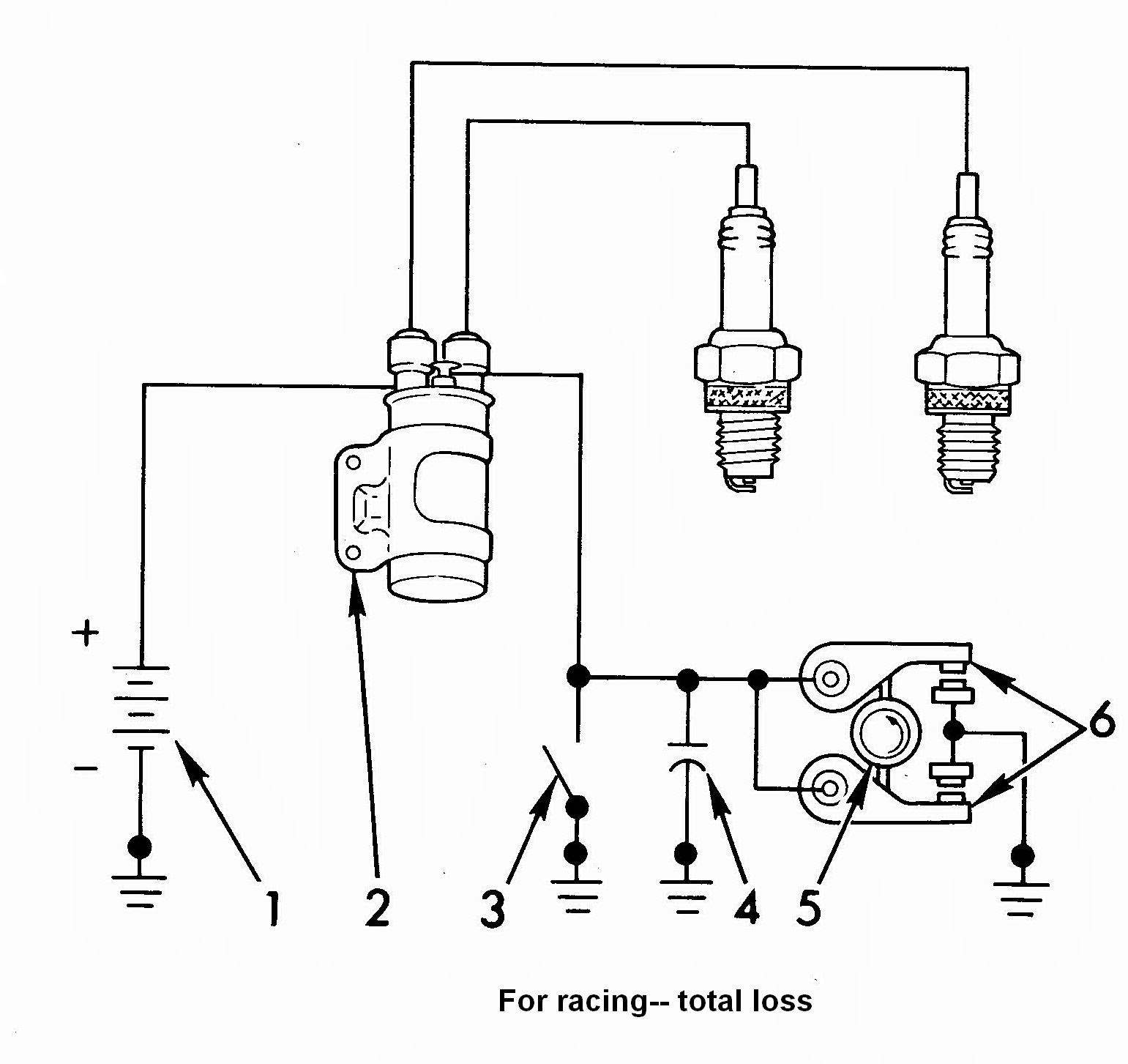
This diagram will show you the wiring connections between the ignition coil, distributor, spark plugs, and ignition wires. You will also see the power source for the ignition coil, which could be either a battery or a capacitor. The diagram will also include the type of spark plug used, the firing order of the cylinders, and the capacitor ratings.

Chevy 350 Ignition Coil Wiring Diagram Free Wiring Diagram
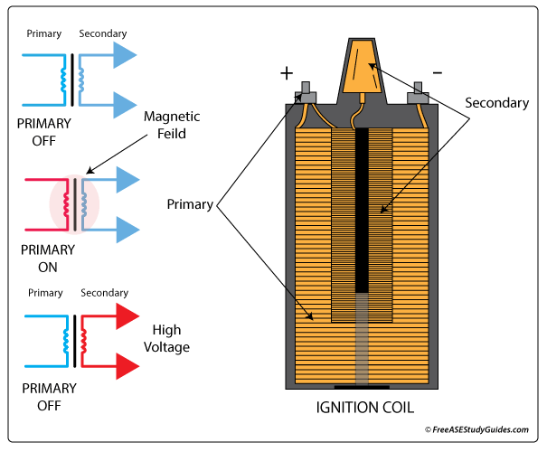
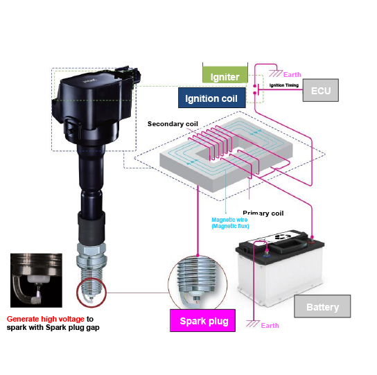
If a coil of wire is exposed to a magnetic field and the magnetic field then changes (or moves), it creates an electric current in the coil of wire. This process is known as 'inductance'. This can be demonstrated simply by moving a permanent magnet across a coil. The movement or change in the magnetic field or magnetic flux induces an.

2.7t Ignition Coil Wiring Diagram
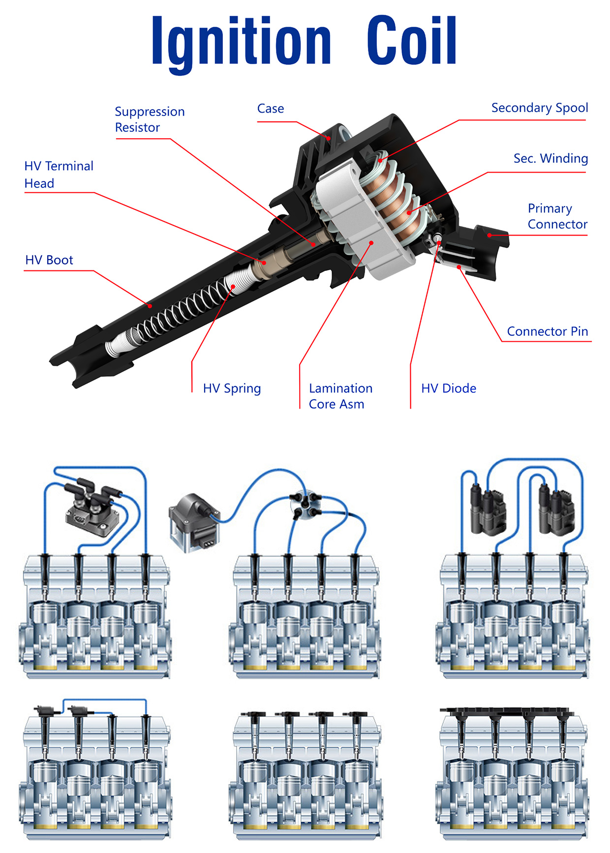
an ignition coil is a crucial component of a vehicle's ignition system that transforms low voltage from the battery into high voltage for spark production. It is vital in generating sparks at the spark plugs to initiate combustion. The ignition coil consists of primary and secondary windings, a core material, and a high-voltage output terminal.

Ignition Coil Wiring Diagram Chevy Ford Ignition Coil Wiring Diagram
Contents An ignition coil (also called induction coil) transforms the battery's voltage to the very high voltage required to generate an electric spark to ignite the fuel. At some point, you will need to replace a failing ignition coil in your car. In that case, you will need to wire the ignition coil correctly.
Ignition Coil Wiring Diagram Honda 3wire Ignition Coil Wiring Diagram
Connected to the battery is the ignition switch. Just like your basic switch at home, the ignition switch allows you to turn on or off the flow of electrical current into other ignition parts. Once current is allowed to flow after the switch is turned on via a key system or button, current should flow into the ignition coil.

2.0 Tsi Ignition Coil Wiring Diagram
An ignition coil (or spark coil) is nothing more than a low frequency auto-transformer with a relatively high turns ratio. The transformer typically has only a dozen or so turns on the primary but many thousands on the secondary.. While the circuit diagram is relatively straightforward, it is poorly designed and the transistor will see.

Wiring Diagram Ignition Coil
Published on: October 27, 2022 4 min read Contents Below, ill cover the 3-wire ignition coil with a diagram of its wiring and some useful information. The purpose of an ignition coil is to produce high voltage for spark plugs. However, the ignition coil pins must be correctly connected to other electrical components.

Basic Ignition System Wiring Diagram Easy Wiring
An ignition Coil is (also called a spark coil) an induction coil which is used to increase the low voltage of the battery (12 Volt) to a very high voltage ( about 50,000 Volt) to produce a spark within the engine cylinder for the combustion of fuel. It is used in automobile ignition systems. We can also say that it is a short step-up transformer.
4.0l engine diagram
1 Disconnect the negative terminal on your battery. Locate your battery in either the engine bay or the trunk of the vehicle. It looks like a rectangular box with two posts (terminals) sticking out of the top of it. The terminals will be labeled with a plus (+) sign on the positive post and a minus (-) sign on the negative one.
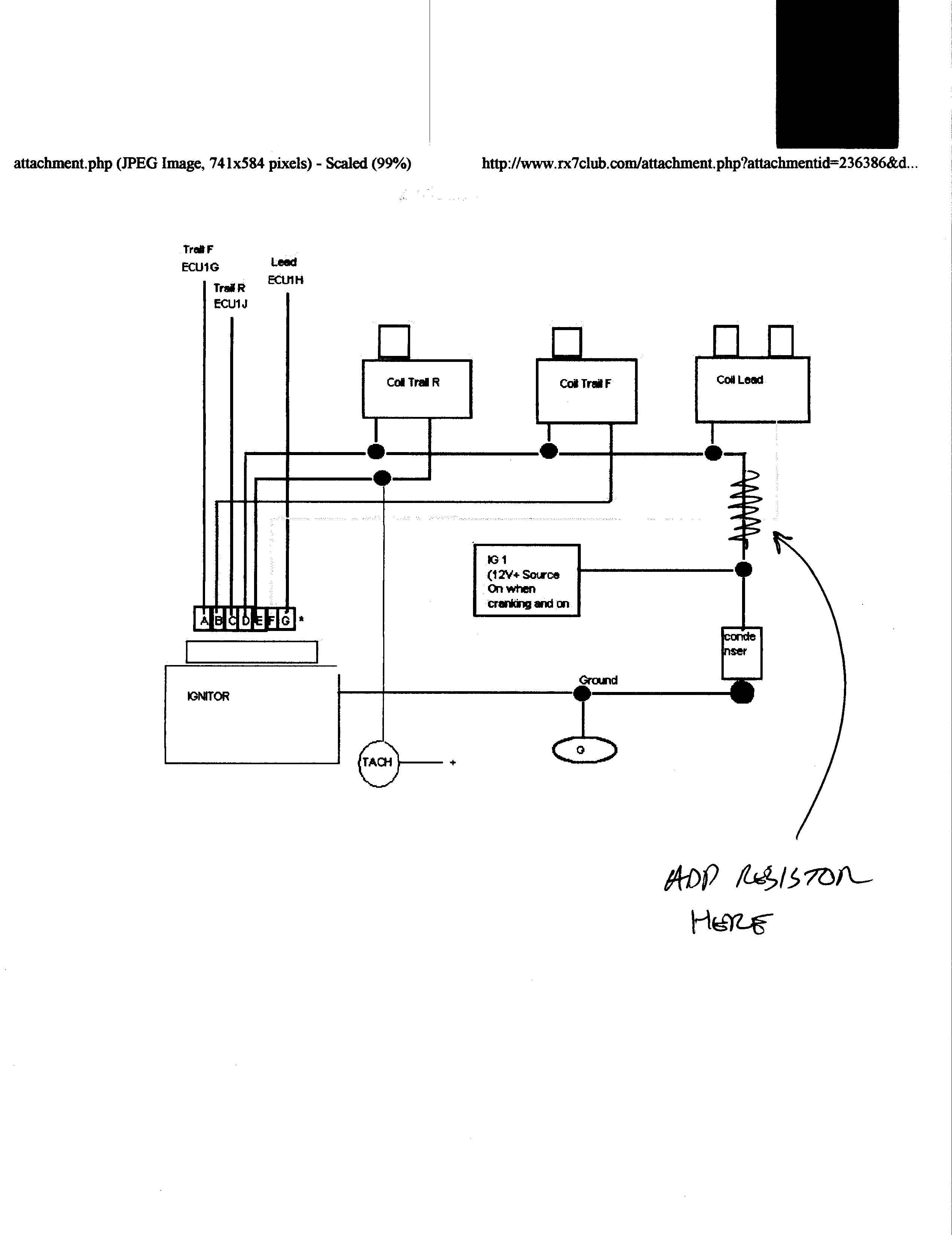
FD ignition, coil wiring help please Mazda RX7 Forum
This diagram typically includes components such as an ignition coil, spark plug wires, a distributor, a crankshaft position sensor, and the ICM itself. It shows the connections among these components, so you can wire them correctly. When working with ICMs, it's helpful to know some common features: Controls the ignition process Manages spark timing
Ignition Coil Wiring Diagram Mg Coil Wiring Diagram Fusebox And
Published on: October 27, 2022 5 min read Contents This article will provide some need-to-know information about the 4-wire ignition coil diagram. The ignition coil is the heart of the ignition system, and improper ignition coil wiring can cause wrong electronic ignition, leading to cylinder misfires.
Circuit Diagram Car Ignition
Contents show The ignition system is one of the most important systems used in the I.C engines. The spark-ignition engine requires some device to ignite the compressed air-fuel mixture. The ignition takes place inside the cylinder at the end of the compression stroke, the ignition system serves this purpose.
Electronic Ignition Coil Wiring Diagram Powerspark Ignition Blog The
The ignition system is a crucial component of any gasoline-powered engine, providing the high voltage necessary to ignite the fuel-air mixture in the engine's combustion chambers. In this video,.
Coil Wiring Diagram Cadician's Blog
The basic principle of an ignition coil To produce the required high voltages, ignition coils make use of the relationships that exist between electricity and magnetism. When an electric current flows through an electrical conductor such as a coil of wire, it creates a magnetic field around the coil (Figure 2).
Ignition Coil Technology NGK
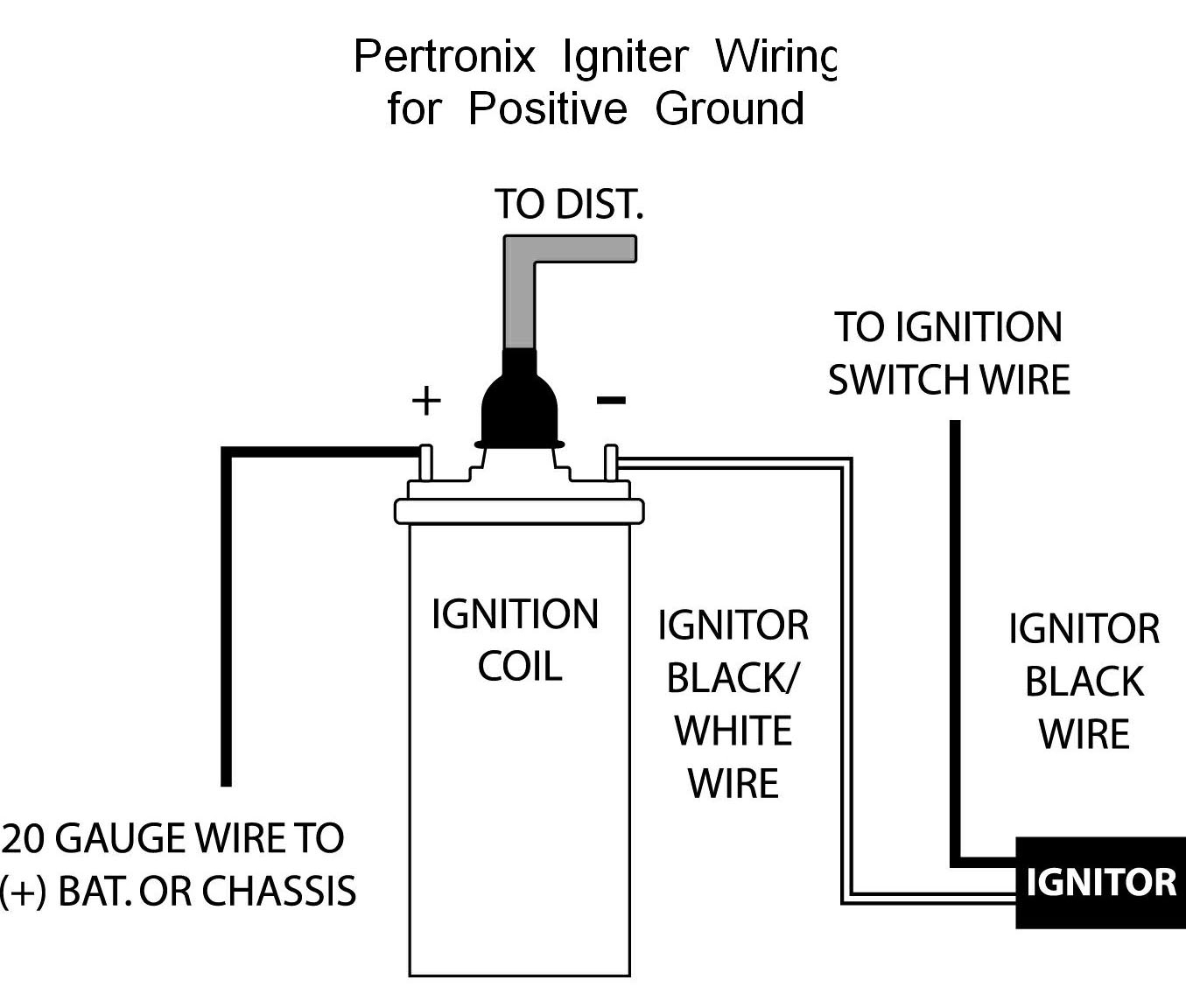
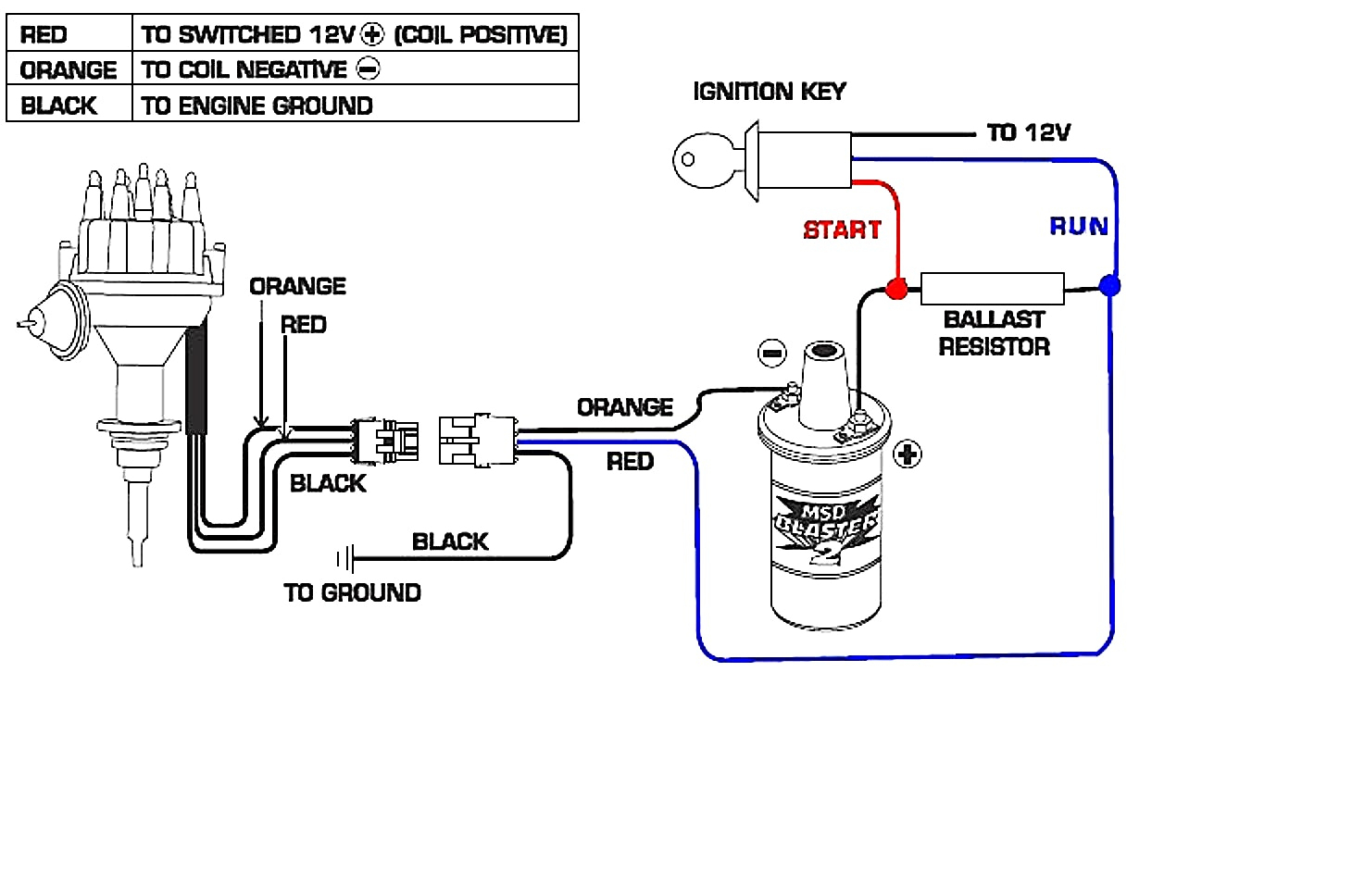
These may include a wiring diagram, a set of pliers, wire strippers, electrical tape, and the ignition coil itself. 2. Locate the ignition coil. The ignition coil is usually located near the engine's distributor. It is a cylindrical-shaped component with two terminals, a positive (+) terminal and a negative (-) terminal. 3. Study the wiring.